The designer of this radio uses for receiver number 2 (right) a loop (frame) antenna, for receiver number 1 (left) a a 20 meters outside antenna (wire).
Receiver 1 generates a supply voltage of approx. 900 mV under load of receiver number 2.
Adjust the variable 250 kOhms resistor to approx 50 % of the voltage generated by receiver number 1 voltage (measured at + pole). Best value for 10 kOhms trim pot is 3 to 6 kOhms.

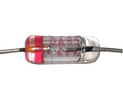
Do not use electrolytic capacitors for the 0.1 uF capacitors. Do not forget to install the 1 nF capacitor. Attention for the polarity of the diode (AA112, AO85, AA119...) in receiver nr 1.
Source:
http://pe2bz.philpem.me.uk/Comm/-%20Receivers/-%20Crystal/Prj-058-WithAF-Amp/dt.htm
Off topic:

Canal in Den Haag (Zuidwal / Dunne Bierkade), 7 Sep. 2017
This comment has been removed by a blog administrator.
ReplyDelete